
Principles, Functions & One-Way Control Applications
Hydraulic systems are designed to control energy in motion. Pressure, flow, and direction must be stable, predictable, and safe. Among directional control valves, hydraulic check valves have a simple structure but play an important role.
Hydraulic check valves prevent backflow. They keep fluid moving in the correct direction and help protect components, hold pressure, and stabilize actuator movement. This helps prevent pressure loss, unstable movement, or damage to pumps and motors.
Directional control valves guide hydraulic fluid through the system. By controlling flow, they regulate actuator movements, such as cylinders extending or holding position. Proper flow paths are essential for stable operation.
Check valves differ from spool or solenoid valves. They do not switch flow paths actively. Instead, they automatically allow or block flow depending on pressure. Because of this, check valves are mainly used to support system safety and stability rather than control main flow.
In practice, check valves can be installed at pump outlets, between branches, in return lines, or inside integrated valve assemblies. They always allow flow in one direction and block it in the opposite direction.
A hydraulic check valve lets fluid flow in one direction and stops backflow. It works automatically using fluid pressure, often with a spring-loaded valve element.
It can also be called a hydraulic non-return valve. Names may vary, but the basic operation is the same: the valve opens when the inlet pressure exceeds the set opening pressure. If fluid tries to flow backward, the valve element presses against the seat, blocking the flow.
Although a hydraulic check valve is designed to allow flow in one direction, it is not a zero-resistance component. When fluid passes through the valve, a pressure drop is always present. Pressure drop directly affects system efficiency, heat generation, and actuator response.
The pressure drop across a hydraulic check valve mainly occurs because the flowing fluid must overcome the spring force, internal friction, and flow restrictions inside the valve. Even after the valve is fully open, the flow path is narrower and less streamlined than a straight pipe. This creates turbulence and energy loss, which appears as a pressure drop.
In low-flow or low-pressure systems, the pressure drop may be negligible. However, in high-flow circuits or energy-sensitive systems, an improperly selected check valve can cause unnecessary power loss and increased oil temperature. For this reason, pressure drop should be considered alongside opening pressure when selecting a hydraulic check valve.
In practice, manufacturers provide pressure drop curves showing the relationship between flow rate and pressure loss. These curves are more reliable than nominal values and should be used during system design, especially for continuous-duty or high-flow applications.
The function of a check valve is simple, but it affects the system in many ways. Common functions include:
Check valves usually operate quietly and are not noticeable during normal operation. Their effect becomes clear when pressure changes suddenly, flow stops, or loads act on the system. Without them, short-term pressure fluctuations can cause long-term mechanical issues.
A check valve works based on a balance of forces on its valve element, usually a ball or poppet.
The minimum pressure to open the valve is called the opening pressure. It depends on the spring force, valve weight, friction, and seat area. Choosing the correct valve is important. If the opening pressure does not match system conditions, it can cause vibration, delayed response, or energy loss.
Hydraulic schematics use standardized symbols defined by ISO 1219-1 to represent check valves. Reading these symbols correctly is a basic requirement for anyone working with hydraulic valve circuits. Misidentifying a check valve on a drawing leads to incorrect installation, wrong flow direction, or overlooked pilot connections — all of which can cause system failure.
The core symbol for a standard check valve is a ball resting against a seat, drawn as a small circle touching a V-shaped line. The V points in the direction that flow is blocked. Flow passes in the opposite direction — from the ball side, pushing it off the seat.
Adding a spring to the symbol indicates that the valve requires a minimum pressure (the opening pressure) to unseat the ball or poppet. In practice, most hydraulic check valves include a spring. It is good practice to note the spring setting next to the symbol on the schematic — for example, “0.5 bar” or “3 bar” — so that maintenance personnel know the intended cracking pressure without having to look up the part number.
The symbol for a pilot operated check valve adds a dashed pilot line connecting to the valve body. This line indicates that an external pressure signal can mechanically open the valve to allow reverse flow. The pilot line is drawn at a right angle to the main flow path and terminates with a small arrow pointing at the check valve element.
A double pilot operated check valve — commonly used in directional control valve circuits as a hydraulic lock — shows two check valves facing opposite directions, each with a cross-connected pilot line from the opposing side. When pressure is applied to one side, the pilot signal opens the opposite check valve, allowing controlled flow in both directions while holding position when the directional valve is centered.
A shuttle valve is a specialized check valve variant with two inlets and one outlet. Its symbol shows two opposing check elements feeding into a single line. The highest pressure from either inlet passes through to the outlet. Shuttle valves are used in load-sensing circuits and pilot pressure selection — for example, feeding the highest working pressure from multiple valve sections back to a load-sensing pump compensator. In multi-spool monoblock directional control valves, shuttle valves can be daisy-chained across spool sections to select the highest load signal automatically.
Hydraulic check valves are usually divided into two categories: standard (non-piloted) and pilot-operated.
Standard check valves rely only on pressure difference and spring force.
Common designs include:
They can be installed in pipelines, modular blocks, or base-mounted assemblies.
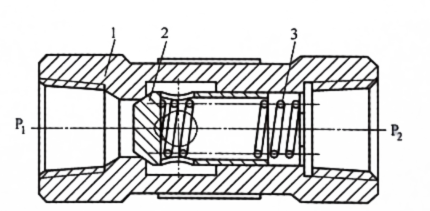
The valve body forms the outer casing of the check valve and is also the main flow channel for the hydraulic oil.
The valve body has an inlet (P₁) at one end and an outlet (P₂) at the other. The valve insert and spring are located in the middle section. The inner surface of the valve body is precision-machined to ensure the coaxial movement of the valve insert and the reliability of the sealing surfaces.
The component shown in the center of the illustration is the valve insert (also called a valve disc or valve insert assembly).
Under hydraulic pressure, the valve insert moves axially, and its front end seals against the valve seat. Once the valve insert is in contact with the valve seat, the flow path is closed, preventing backflow.
This design features an axially guided valve insert, which, compared to a freely supported design, allows for more stable movement of the valve insert and is less susceptible to vibration under medium to high flow conditions.
The valve seat is located in the valve body and is in direct contact with the sealing surface of the valve insert.
When back pressure occurs or system pressure drops, spring force and hydraulic pressure act together to press the valve insert against the seat. This creates a reliable seal and prevents backflow of hydraulic oil.
The machining accuracy of the valve seat directly affects the sealing performance and the service life of the check valve.
The spring is located behind the valve insert and is a key component for the automatic closing function of the check valve.
The main functions include:
The higher the spring stiffness, the higher the pressure required to open the valve and the greater the pressure loss during forward flow.
When hydraulic oil flows from P₁ to P₂, the pressure overcomes the spring force and pushes the valve spool away from the valve seat, creating a flow path. The hydraulic oil flows through the gap around the valve spool to the outlet.
When hydraulic oil attempts to flow from P₂ to P₁, the pressure and spring force work together to press the valve spool firmly against the valve seat. This completely closes the flow path and prevents backflow.
In industrial use, opening pressure is usually 0.04–0.4 MPa and can be adjusted by changing spring stiffness. Performance depends on valve design and system conditions.
The valve body, poppet, seat, and spring must withstand the system’s working pressure, temperature, and fluid chemistry. Material choice directly affects service life, sealing reliability, and corrosion resistance.
Carbon steel is the standard for general industrial hydraulic systems operating with mineral-based hydraulic oil at moderate temperatures (–20 °C to +80 °C). It offers good strength-to-cost ratio and is compatible with most hydraulic fluids meeting ISO 6743-4 (HM grade).
Stainless steel (typically 316 or 316L) is specified for offshore, marine, food-grade, and chemical processing applications where exposure to water, salt spray, or corrosive fluids is expected. The higher material cost is justified by significantly longer service life in aggressive environments.
Aluminum is occasionally used in low-pressure, weight-sensitive applications — such as mobile equipment where reducing valve weight matters. It is not suitable for high-pressure circuits or environments with abrasive contamination.
Brass appears in some low-pressure hydraulic and pneumatic crossover applications. It provides moderate corrosion resistance but is not recommended for system pressures above 250 bar.
Spring materials are equally important. Standard springs use music wire or chrome-vanadium steel. For high-temperature or corrosive conditions, Inconel or stainless steel springs prevent fatigue failure and maintain consistent opening pressure over time. A weakened spring leads to reduced closing force and eventual internal leakage — a failure mode covered in the troubleshooting section below.
Installed at pump outlets, check valves prevent backflow and pressure changes after the pump stops, protecting pumps and motors.
Check valves prevent pressure interference between different branches. This is useful in systems with multiple actuators at different pressures.
In return lines, check valves can maintain back pressure, improving smooth operation and handling load changes.
Check valves are often combined with other valves (throttle, sequence, or flow control) to form assemblies like throttle-check valves or sequence-check valves.
In addition to its basic one-way function, a pilot-operated check valve also allows for controlled reverse flow when needed.
In normal operation, it functions like a standard check valve, allowing flow in only one direction. When a pilot pressure is applied to the control port, the internal piston mechanically opens the valve, thus allowing bidirectional flow.
This design is typically used in load-holding circuits.
The pilot pressure is usually taken from the hydraulic line and must reach a certain percentage of the system pressure to ensure reliable opening. In many designs, this percentage is between 30% and 50%, but the exact value depends on the valve design and manufacturer specifications.
A pilot operated check valve has three ports: inlet, outlet, and pilot. In the forward direction (inlet to outlet), it behaves exactly like a standard check valve — fluid pressure overcomes the spring and opens the poppet. In the reverse direction, the poppet is held shut by both spring force and trapped load pressure.
When pilot pressure is applied, a pilot piston inside the valve body pushes against the main poppet through a mechanical linkage (typically a push pin). This unseats the poppet and creates a reverse flow path. The pilot pressure required to open the valve depends on the pilot ratio — the area ratio between the pilot piston and the main poppet. A pilot ratio of 3:1 means that a pilot pressure equal to one-third of the trapped load pressure (plus the spring force) is sufficient to open the valve. Common pilot ratios in industrial hydraulic check valves range from 3:1 to 8:1, with 4:1 being typical for general-purpose applications.
If the pilot ratio is too low, the system may need excessive pilot pressure to open the valve. If it is too high, the valve can become unstable under fluctuating loads, opening and closing rapidly — a condition sometimes called “ratcheting” or “chattering” that is covered in the troubleshooting section below.
A single pilot operated check valve manages flow in one actuator line. It is used with single-acting cylinders or on one port of a double-acting cylinder where only one direction requires load holding.
A double pilot operated check valve packages two units in a single housing, with cross-connected pilot lines. When the directional control valve shifts to extend the cylinder, pressure on the cap-end line simultaneously pilots open the rod-end check valve, allowing fluid to return. When the directional valve centers, both check valves close and lock the cylinder in position.
This configuration is commonly referred to as a “hydraulic lock.” Our P40 series and P80 series monoblock directional control valves offer hydraulic lock as an option on the A and B work ports — this is exactly a double pilot operated check valve integrated into the valve body, eliminating external plumbing and reducing potential leak points.
This comparison comes up frequently, and it is worth clarifying because the two valves solve different problems despite both being used in load-holding circuits.
A pilot operated check valve is either fully open or fully closed. It does not meter flow. It holds a load with near-zero leakage when the pilot signal is removed, and releases the load instantly when the pilot signal is applied. This works well for applications where the load is always positive (always pushing in the same direction) and there is no need to control lowering speed — clamping circuits, vertical presses, or locked-position holding.
A counterbalance valve is a modulating valve. It can hold a load, but it also controls the speed at which the load moves by metering the return flow. It prevents “running away” when a load reverses from positive to negative (for example, gravity pulling a boom down faster than the pump can supply oil). The cost is higher, the leakage rate is slightly greater, and the pressure setting requires more careful tuning — but for mobile equipment like excavators, cranes, and aerial platforms, the motion control capability is essential.
The rule of thumb: if you need to hold a load in place and release it on command, a pilot operated check valve is the simpler and more cost-effective choice. If you need to control load speed during movement — especially with over-center or gravity loads — a counterbalance valve is the correct solution. When diagnosing boom drift on excavators, distinguishing between these two valve types is the first step in identifying the root cause.
Selecting a hydraulic check valve requires more than just matching nominal pressure and port size. Several operating factors influence its performance.
Proper sizing contributes to noise reduction and extended service life.
Check valves are directional valves. Incorrect installation can obstruct flow or cause malfunctions. Flow direction markings must always be checked during installation and maintenance, especially in circuits connected to pumps or carrier components.
In late 2023, a material handling facility in Ohio experienced repeated pressure losses in its vertical lifting system. Even with normal pressure readings at system startup, the carrier’s hydraulic cylinders slowly lowered during idle operation.
Further investigations revealed backflow in the return circuit under static load. The existing directional control valve was inadequate.
Check valves fail quietly. They do not generate alarm codes. They do not make obvious noise. What they do is allow small amounts of fluid to pass in the wrong direction, and that backflow causes symptoms that often get blamed on other components. Our experience servicing systems across construction, manufacturing, and material handling — documented in detail across our valve diagnostics guide and relief valve troubleshooting guide — shows that check valve issues follow a consistent pattern.
The cylinder slowly creeps or settles when the directional valve is centered. This is the single most common check valve complaint. The cause is usually a worn or contaminated poppet-to-seat interface that no longer seals completely. Even a scratch as fine as 10 microns across the seat can allow enough leakage to cause visible drift over minutes. Before replacing the check valve, rule out cylinder piston seal bypass by isolating the cylinder from the circuit — disconnect the hoses and cap the ports. If the cylinder holds, the leak is upstream in the valve circuit.
If the pump makes grinding or whining sounds during startup but quiets down after several seconds, suspect a failed pump outlet check valve. When this valve cannot hold fluid in the lines during shutdown, the lines drain back to the tank through the pump. On the next startup, the pump must draw fluid up from the reservoir while compressing the air that has entered the empty lines. In systems where the pump is mounted below the valve manifold, a functional check valve downstream of the pump is essential to keeping the lines primed. One major plywood processing facility replaced four pump housings — cracked from repeated pressure spikes — before discovering that the pump outlet check valve had lost its spring and poppet entirely. That single $150 component failure cost the plant over $15,000 in replacement pumps and an estimated $50,000 in machine downtime.
A bypass check valve is typically installed in parallel with the heat exchanger. If the heat exchanger becomes restricted (contamination, internal scaling), the check valve opens to route oil around it, protecting the cooler tubes from overpressure. If this check valve is missing, plugged, or has an incorrect spring setting, the tubes can rupture. If your system has unexplained cooler failures, verify that the bypass check valve exists, is installed in the correct direction, and opens at the rated differential pressure.
Accumulators store pressurized fluid for emergency functions or pulsation dampening. A check valve between the pump and accumulator prevents the stored energy from flowing back through the pump when the system shuts down. If this valve leaks, you will observe the accumulator gauge slowly dropping after shutdown. In safety-critical systems — such as emergency brake circuits or aerial platform lowering systems — this failure mode is a direct safety hazard and should trigger immediate valve replacement.
When lowering a suspended load through a pilot operated check valve, the load may descend in a series of jerky, stop-start movements rather than moving smoothly. This “ratcheting” occurs because the pilot pressure builds, opens the check valve, the load moves, the pilot pressure drops (as the load moves away from the pump flow), the check valve closes, pressure rebuilds, and the cycle repeats. The root cause is often an oversized check valve or a pilot ratio that does not match the cylinder’s area ratio. In these cases, a counterbalance valve — not a pilot operated check valve — is the correct solution, as described in the pilot operated check valve section above.
For any suspected check valve failure, the diagnostic sequence is:
Contamination is the number one cause of check valve failure across every industry we serve. Maintaining fluid cleanliness to at least ISO 4406 18/16/13 — or better for servo-quality systems — prevents the vast majority of issues. For a full maintenance framework, see our guide on essential hydraulic parts and maintenance prioritization.
Testing verifies two things: forward flow behavior (does the valve open at the correct pressure with acceptable pressure drop?) and reverse sealing (does the valve block backflow at rated pressure with zero or negligible leakage?).
Per ISO 6403 (the international standard for hydraulic valve testing), the test circuit consists of a hydraulic power source, a flow meter, pressure gauges upstream and downstream of the test valve, and a load valve to control back pressure. The test procedure increases flow through the valve in steps while recording the pressure drop at each flow point. The resulting curve should match the manufacturer’s published pressure drop data within acceptable tolerances.
For reverse leakage testing, pressurize the outlet side to the valve’s rated working pressure with the inlet side connected to a collection vessel. Measure the collected fluid over a defined time period. A new check valve should show effectively zero leakage. A used valve showing more than 1–2 drops per minute at rated pressure should be considered for replacement.
If bench testing is impractical, you can perform a functional check in the system. Install a pressure gauge immediately upstream and downstream of the check valve. With the system running, verify that the upstream pressure exceeds the downstream pressure by the expected opening pressure plus flow-induced pressure drop. Then shut off flow and observe the downstream gauge: if pressure decays steadily, the check valve is leaking in reverse.
For pump outlet check valves, a simple indicator is pump shaft rotation. After system shutdown, watch the pump shaft or motor fan. If the shaft rotates backward briefly, the check valve is not sealing and accumulated pressure is flowing back through the pump — a clear replacement signal.
From a system design perspective, selecting a check valve requires considering performance requirements, operating conditions, and overall system costs.
A clear classification of valve categories helps engineers and maintenance teams effectively narrow down the selection. Specialized product lines, such as hydraulic valve solutions, often serve as a reference for system design or component replacement.
Product Availability and Technical Resources: Modern hydraulic systems require components that function reliably under a wide range of conditions. Hydraulic88 offers valve options for common industrial applications, focusing on functionality, application compatibility, and cost-effectiveness.
A well-thought-out valve selection process contributes to smooth system upgrades, maintenance schedules, and component replacements throughout the entire lifecycle of the hydraulic system.
Hydraulic check valves may seem simple, but they play a crucial role in system stability, component protection, and reliable operation. By preventing unwanted backflow, they protect pumps, isolate circuits, and control loads in a variety of applications.
Knowing how different check valves work, where they are used, and how they are installed helps engineers avoid common system issues, thereby improving system reliability and avoiding unnecessary complexity.
Further technical aspects: With the advancement of hydraulic systems, check valves are increasingly being integrated into compact manifolds and control valves. These designs reduce potential leakage points and improve response speed. However, since long-term performance data for some integrated configurations are still being optimized, an application-specific evaluation is essential.
A standard check valve allows flow in one direction only, based on pressure difference and spring force. A pilot operated check valve adds a third port (the pilot port) that accepts an external pressure signal. When pilot pressure is applied, it mechanically opens the valve to allow reverse flow. This allows the valve to hold a load when the pilot signal is removed and release it on command. Pilot operated check valves are commonly used in cylinder load-holding circuits, including the hydraulic lock option available on monoblock directional control valves.
The most common cause is contamination. Particles as small as 10 microns can lodge between the poppet and seat, preventing a complete seal. Other causes include wear or scoring on the seat surface, a weakened or broken spring that cannot generate sufficient closing force, and corrosion in environments where the valve material is not compatible with the hydraulic fluid. Maintaining fluid cleanliness to ISO 4406 standards is the most effective prevention measure.
The most critical location is immediately downstream of the hydraulic pump, where the check valve prevents pressure spikes from traveling back to the pump and keeps lines primed during shutdown. Other common positions include between parallel pump circuits (to prevent a running pump from forcing oil into a standby pump), in parallel with heat exchangers (as a bypass to protect against overpressure), at accumulator inlets (to retain stored energy), and at cylinder ports (as load-holding devices). The correct placement depends on the circuit design — always refer to the hydraulic system schematic before installing.
Cracking pressure (also called opening pressure) is the minimum pressure differential across the valve required to push the poppet or ball off its seat and begin allowing flow. In industrial hydraulic check valves, cracking pressure typically ranges from 0.04 to 0.4 MPa (approximately 0.4 to 4 bar), depending on the spring stiffness. A lower cracking pressure reduces forward flow resistance but may compromise sealing reliability under low back-pressure conditions. The correct cracking pressure depends on the specific circuit function.
Technically, a check valve with a spring setting can function as a low-pressure relief valve — it will open when upstream pressure exceeds the spring force, allowing fluid to bypass. This is commonly done in heat exchanger bypass circuits. However, check valves are not designed for precise pressure regulation. They have poor pressure override characteristics (the pressure rises significantly as flow increases) and are not suitable as primary system protection. For safety-critical pressure control, always use a purpose-built hydraulic pressure relief valve.
A pilot operated check valve is a non-modulating valve — it is either fully open or fully closed. It holds loads with near-zero leakage but cannot control movement speed. A counterbalance valve is a modulating valve that meters return flow, preventing load runaway under gravity or over-center conditions. Use a pilot operated check valve when you need to lock a position (clamping, pressing, static holding). Use a counterbalance valve when you need to control movement speed under varying loads (crane booms, excavator arms, aerial platforms). Choosing the wrong type is a frequent cause of jerky actuator movement and, in mobile equipment, a potential safety concern during load lowering.
The standard method follows ISO 6403. Connect the check valve to a test bench with a flow meter, upstream and downstream pressure gauges, and a load valve. Increase flow in steps to verify the forward pressure drop curve matches manufacturer data. For reverse sealing, pressurize the outlet side to rated pressure and measure any leakage at the inlet. A functional in-system check involves installing gauges on both sides of the valve and monitoring for pressure decay after flow stops. For pump outlet check valves, observing backward shaft rotation after shutdown is a quick indicator of failure.